A mounting system is only as strong as its weakest connection, and wind and snow find it quickly. Simulation lets you find it first, on a computer, before you pay for prototypes and test rigs. This guide covers how loads travel through a system, where systems usually give way, which load cases matter, and what simulation can and can't tell you.
How loads travel through a mounting system
Snow presses down on the modules. Wind pushes down on some parts of an array and pulls up on others. That upward pull, called uplift or suction, is often the critical case, especially at roof edges and corners.
Either way, the load follows the same path: from the module, through the clamps, into the rails, down through the roof hooks or brackets, and into the roof structure. Every connection on that path needs checking, not only the rail.
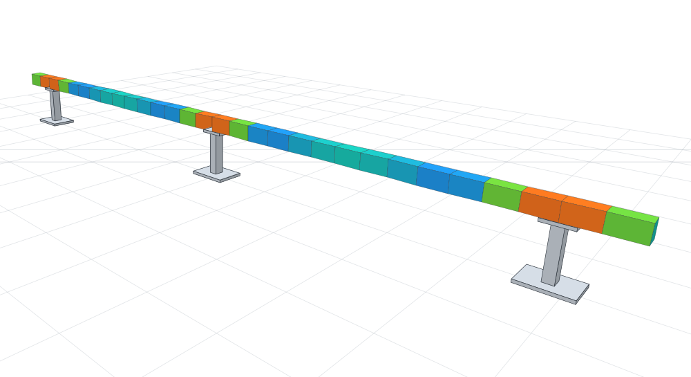
The usual weak points
- Rail bending and deflection. The span between roof attachments decides how much the rail bends. A rail can be strong enough and still sag too far.
- Clamps. Under uplift, the clamps hold the module frame down. Clamping outside the module maker's approved zones, or with too short a clamp, can let a module slip or pull free.
- Roof hooks and brackets. A tile hook carries load through a lever arm, so it bends. Under heavy snow, a hook that bends too far can press on the tile below and crack it.
- Fasteners. T-bolts in rail channels, and screws into rafters or purlins, can pull out or shear.
- Ground-mount frames. Posts, piles and bracing carry the whole array. On tilted frames, wind flowing under the modules creates uplift and tries to overturn the frame.
The load cases that matter
The load values come from the standards in each market. In Europe, snow loads come from EN 1991-1-3 and wind actions from EN 1991-1-4, with each country's national annex setting its values. In the US, ASCE 7 covers both. The values depend on location, terrain, height above ground, and roof shape and pitch.
A typical check covers:
- Self-weight plus snow, pressing down.
- Wind pressure, pressing down.
- Wind suction, pulling up, usually worst at roof edges and corners.
- Combinations of these with the safety factors from EN 1990, or the ASCE 7 combinations, to check strength.
- Deflection under unfactored loads, to check serviceability.
Because suction is higher at edges and corners, a system often needs closer attachment spacing there than in the middle of the roof.
What simulation gives you
- Stress and safety factors in every part, for each load case.
- Deflection, so you know whether the rail sags too far between attachments.
- Maximum spans: how far apart roof attachments can be for a given snow and wind level. This becomes the span table installers use on site.
- Design comparisons before you pay for tooling, such as two rail profiles or a thicker hook.
What simulation doesn't replace
Many markets and customers still expect physical tests, or a calculation signed by a qualified engineer. Simulation doesn't remove that step, but it makes the test more likely to pass the first time and tells you which configuration to test.
Some behaviour also needs care. Clamp slip depends on friction, and contact between parts is an approximation, so we calibrate the model against a test where one exists. The roof structure itself is the building engineer's responsibility.
What to prepare
- CAD of the system, including clamps, hooks and fasteners.
- Materials and grades.
- The markets you sell in, and the standards that apply there.
- The worst site you want to cover: snow zone, wind zone, terrain and building height.
- The attachment spacings you want installers to be able to use.
- Any test data you already have.
If that list looks long, start with the CAD and the markets. We'll propose the load cases for you to confirm.